Saturday, July 26, 2014
Little Green Man Prototype Build, Part 8, Ears and Antennas
The small ears are glued 3/4" up from the bottom of the nose cone shoulder on either side of the eyes.
Some primer was removed down the root edge glue line.
"Test" eye covers were set in place with a glue stick.
These will be printed on 110 lb. card stock on the finished model.
Antenna holes were drilled by spinning a small diamond file.
The antennas have to be soft and flexible, you wouldn't want a hard spike on the nose of a model.
Pipe cleaners could work great for this. We called them pipe cleaners when I was a kid, now they are called "Chenille Wires".
For the "ball ends" of the antennas, turn the pipe cleaner around the top of some needle nosed pliers.
The inside wire of the pipe cleaner inserts and stays in the small hole drilled earlier. They'll be glued in place after the model gets it's final green color coat.
One antenna is curved and bent to the side. The antenna on the right is straighter. Why? It's just more cartoon-ey.
The antennas were pulled out and the eye covers removed.
White undercoats were applied.
Friday, July 25, 2014
Little Green Man Prototype Build, Part 7, Nose Weight and Nose Plug Assembly
The screw eye is turned into the nose plug circle until the thread line is almost gone.
A glue fillet is added to both sides.
The clay is pressed into the drilled center of the nose cone.
Look inside the nose cone and you can see the glue line around the edge for the plug and screw eye.
Press the plug into the hole and into the glue line.
Recess the plug inside the hole to allow for an additional fillet around the edge.
Looking ahead -
I found an old can of Key Lime Rustoleum Painter's Touch. This is an old label before the 2X was added. This same can has got a lot of use over the past few years. It was used on the Franken Goblin and Elevate 11 models.
There is plenty of paint in the can, a perfect color for the project.
Thursday, July 24, 2014
Little Green Man Prototype Build, Part 6, Arm and Eye Gluing
The small arms were glued on just above the two front fin legs.
These were set back to the halfway point around the tube, at 180 degrees.
The eyes were a different story.
The larger eye goes to the left of center. The top of the oval is almost even with the top of the nose cone.
Set each eye on the nose cone and lightly trace around with a pencil.
For a flatter gluing surface, the gluing area is sanded flat with 220 grit on a sanding block. Don't sand all the way to the sides of the drawn oval, keep the flat sanded area inside the line by about 1/16".
This flattened oval makes a larger gluing area and allows the flat eyes to better sit into the nose cone curve.
The eyes are glued on.
Note the top of both eyes are turned out. The right eye is set slightly higher than the base of the left eye.
Wednesday, July 23, 2014
Little Green Man Prototype Build, Part 5, Fin and Feet Gluing
The three fin lines were drawn and the primer sanded down for better adhesion.
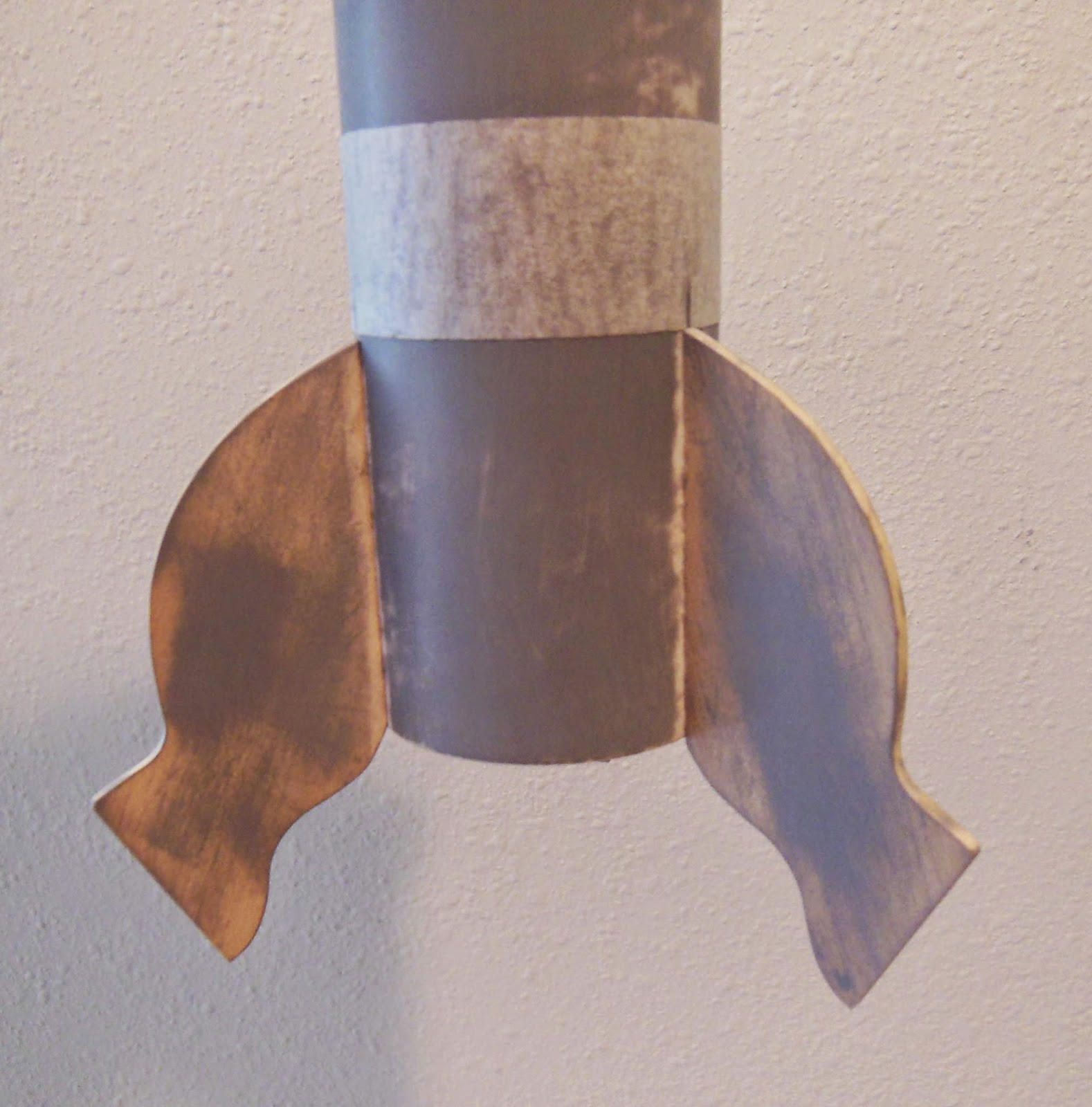
The fins are even with the rear of the tube.
To make positioning easier, the pencil line was extended around the end of the tube. A line was also drawn down the middle of the leading and trailing ledges.
The middle fin lines were simply matched up to the line on the body tube.
To be sure the fin height was the same, a wrap of masking tape was rolled around the tube after the first fin was glued on.
The feet were glued onto the outside edge of the main fin leg.
The "toes" were turned out from the heel end.
The inset picture shows the angle of the glue line.
The launch lug is glued to the root edge of the back third leg.
The fins are even with the rear of the tube.
To make positioning easier, the pencil line was extended around the end of the tube. A line was also drawn down the middle of the leading and trailing ledges.
The middle fin lines were simply matched up to the line on the body tube.
To be sure the fin height was the same, a wrap of masking tape was rolled around the tube after the first fin was glued on.
The feet were glued onto the outside edge of the main fin leg.
The "toes" were turned out from the heel end.
The inset picture shows the angle of the glue line.
The launch lug is glued to the root edge of the back third leg.
Labels:
Build,
Design,
Fin Alignment,
Kit Development,
OR Little Green Man,
Prototype
Location:
Orlando, FL, USA
Tuesday, July 22, 2014
More Little Green Man Test Flights
The Odd'l Rockets Little Green Man had it's sixth successful test flight on July 12 with an Estes B6-4 engine.
All is good, still no damage except for some expected small smoke discoloration.
At the July 14 STEM launch the L.G.M. had it's second C6-5 flight. That's seven stable flights!
The overhead recovery picture is a screen capture of that flight from Roger Smith's Quad Copter video camera. That's an Odd'l Rockets parachute with a spill hole. Roger's video is HERE
The stranger the design, the more test flights are required.
The second prototype flew naked (no paint) on July 20.
The hand shape is more defined and the feet angle is set closer to vertical. The new foot position is less draggy and adds some altitude. Flight eight - stable!
The Estes B6-4 engine popped the parachute at around 350 feet.
The antennas were just stuck in the head holes, not glued in until after painting.
It doesn't look very interesting without the eyes and big mouth.
Monday, July 21, 2014
Little Green Man Promo Film Short
Roger Smith put together a great L.G.M. promotional video.
You can see a C6-5 flight from a quad copter video perspective.
CLICK HERE
This was filmed at the July 14, S.T.E.M. launch.
The music and Theremin sounds make the perfect soundtrack.
Thanks Roger! Great work as always . . .
Sunday, July 20, 2014
Little Green Man Prototype Build, Part 4, Fin Revision and Balsa Laser Layout
The larger lower fins needed some subtle shape change.
For two reasons -
1. More strength after seeing the balsa grain ended up and
2. A better angle for less drag with the "T" foot piece glued to the outside edge.
The original fin is on top, the revised fin is under it.
Here's the revised upper and lower fins.
The fins were photographed with the 1" length for reference.
I can drop the jpeg picture into Corel Draw, size it to the 1" reference line and trace the new shapes.
Looking ahead, I wanted to see how all the balsa would fit on a 3" or 4" widths of balsa sheet for laser cutting.
The top picture shows the pieces set on a 4" width. The length was 7 1/4".
It's like a puzzle. Laying out the pieces takes many tries.
Using cut balsa you can see the correct grain direction.
The pieces have to be spaced so the laser cuts can't overlap.
I ended up fitting them all onto a 3" X 9" area.
On a 36" long balsa sheet I can cut four sets of fins.
Subscribe to:
Posts (Atom)