Showing posts with label Build. Show all posts

Tuesday, September 2, 2014

Flare / Bell Bottom Build, Part 2 Design Process


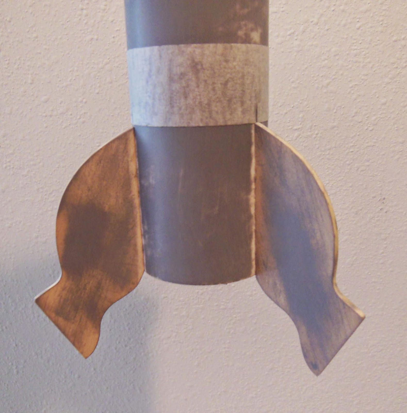
Here's the back view with the shroud over a 5/60 centering ring.
There's no engine hook, the engine is slid in place and gets a wrap of masking tape over the BT-5 tube.

The extended shroud isn't as strong as I would like.


Below the centering ring I'm adding a short "nested" shroud.
This will but up against the centering ring and be even with the back end of the outside shroud.


The entire model was dry fitted to see the finished shape.
I'll probably keep the launch lug short, right beneath the hole in the shroud. It's never easy to trim the lug end even with the angle of the shroud.

Monday, September 1, 2014

Flare / Bell Bottom Build, Part 1 Design Process

Drawing up a shroud can be tough, if you are off by the slightest bit the fit will be poor.
I use the shroud tool on www.payloadbay.com for a start.
But, the shroud will have to be printed later with more than one shroud per sheet of card stock.

The shroud was dropped into Corel Draw and redrawn.
Three shrouds were made, one slightly larger another a bit larger.
One of the three should give a friction fit over the BT-5 body.

The lug hole is pre-punched and will be in the kit.
That small hole is hard to cut out after the shroud is formed. By pre-punching the lug hole I'll have a perfectly round top to the lug recess hole.

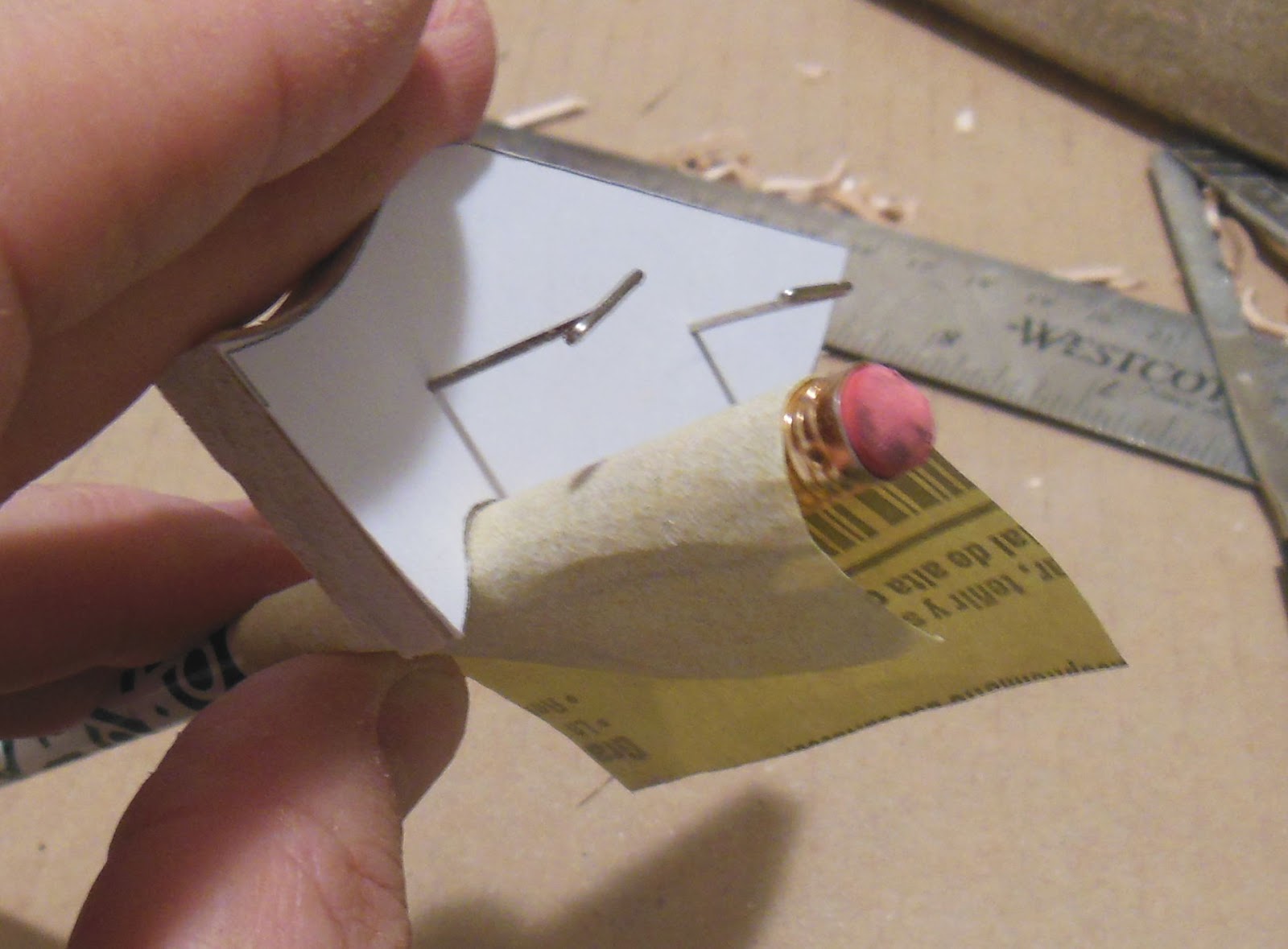
After the shroud is glued up, the straight vertical lines in the lug slot are cut with scissors.
This keeps the shroud stiffer when forming and gluing. If the lug slot were completely cut out (before forming the shroud) it is harder to get it round on the narrow end.

Friday, August 1, 2014

Odd'l Rockets Little Green Man Prototype Finished!


This was a fun one, a little like the Pigasus in some of the design elements.
It uses the same nose cone, engine mount and body tube as the Pig.
I added a white card stock tooth. It looks much better than the clear area on the water slide decal.
There are many visual levels to this design. The eyes are raised, the white tooth looks raised and the small hands aren't in line with the two front legs.

I didn't show it in the build pics, the pipe cleaner antennas were white glued into the holes drilled earlier.

From some angles the LGM looks a little angry.
Straight on it just looks goofy.


Here's the view from the back, I've yet to add the ray gun on the left side.
The angled out feet will provide base drag and could improve stability.
A 12" Odd'l Rockets parachute rounds out the build.

Wednesday, July 30, 2014

Little Green Man Prototype Build, Part 11, Belt and Laser Pistol


The model needed more trim. I added a chrome Monokote trim belt.
The wrap took a few tries, it was hard to get it under the hands.
The belt looked plain so a buckle was added.
The base was a scissor cut piece of 100 lb. white card stock.
The center of the buckle was another piece of chrome Monokote.
EDIT: In the kit, the buckle is an oval shape.

The back of the model didn't have enough detail.
What good is a spaceman without a laser gun?

This gun was drawn up from images found online.
The lower image shows how it will "tuck" under the belt.
It won't really go under the belt. The center strip is cut out and the image is glued on the top and bottom of the chrome strip.

Monday, July 28, 2014

Little Green Man Prototype Build, Part 10, Big Mouth and Eyes

The mouth decal is tall. Before soaking, it's best to pre-cut in two at the small tic marks printed to the side of the decal. The decal separates at the nose cone and body tube joint.

When designing a possible kit, many changes are made in the prototype before the kit design is finalized.
The decal cut joint ended up about 1/8" lower than I had first drawn up.


EDIT: On this first prototype build, I set the lower half of the mouth first. It is actually easier to align both pieces setting down the upper, smaller half of the mouth first.
The lower half of the mouth is positioned first, centered below the eyes and up against the end of the body tube.
I'm tempted to say: "Bwa-ha-ha-ha!
The big mouth is a focal point of the whole design.


The eye covers were cut out of 110 lb. printed card stock and set in place with a glue stick.
Even the glue stick gives a strong hold one the eyes, even over the green paint.

Sunday, July 27, 2014

Little Green Man Prototype Build, Part 9, Paint and Fingernails


White undercoats were sprayed.
Two separate coats, light sanding between coats to remove any glue boogers and rough areas.

The Key Lime Green Rustoleum paint followed.
No masking, just a light green overall. The decals and decor pieces will make the model.


I should have made the fingernails on water slide decal paper.
For the prototype they were cut out of blue trim Monokote.
It was hard to get them to the right oval shape, some were very small.
(In the kit these will be water slide decals) 

Three nails were cut for two hands, six in total.
(In the kit the hands will have just two fingernails) 
12 more were cut for the four nails on the three feet.

They were places on the tip of my hobby knife. Nothing was burnished down until the spacing was right. It took a few tries to get everything in place.

Saturday, July 26, 2014

Little Green Man Prototype Build, Part 8, Ears and Antennas


The small ears are glued 3/4" up from the bottom of the nose cone shoulder on either side of the eyes.
Some primer was removed down the root edge glue line.

"Test" eye covers were set in place with a glue stick.
These will be printed on 110 lb. card stock on the finished model.

Antenna holes were drilled by spinning a small diamond file.

The antennas have to be soft and flexible, you wouldn't want a hard spike on the nose of a model.

Pipe cleaners could work great for this. We called them pipe cleaners when I was a kid, now they are called "Chenille Wires".
For the "ball ends" of the antennas, turn the pipe cleaner around the top of some needle nosed pliers.


The inside wire of the pipe cleaner inserts and stays in the small hole drilled earlier. They'll be glued in place after the model gets it's final green color coat.
One antenna is curved and bent to the side. The antenna on the right is straighter. Why? It's just more cartoon-ey.

The antennas were pulled out and the eye covers removed.
White undercoats were applied.

Friday, July 25, 2014

Little Green Man Prototype Build, Part 7, Nose Weight and Nose Plug Assembly


The screw eye is turned into the nose plug circle until the thread line is almost gone.
A glue fillet is added to both sides.
The clay is pressed into the drilled center of the nose cone.
Look inside the nose cone and you can see the glue line around the edge for the plug and screw eye.

Press the plug into the hole and into the glue line.
Recess the plug inside the hole to allow for an additional fillet around the edge.


Looking ahead - 

I found an old can of Key Lime Rustoleum Painter's Touch. This is an old label before the 2X was added. This same can has got a lot of use over the past few years. It was used on the Franken Goblin and Elevate 11 models.
There is plenty of paint in the can, a perfect color for the project.

Thursday, July 24, 2014

Little Green Man Prototype Build, Part 6, Arm and Eye Gluing


The small arms were glued on just above the two front fin legs.
These were set back to the halfway point around the tube, at 180 degrees.


The eyes were a different story.
The larger eye goes to the left of center. The top of the oval is almost even with the top of the nose cone.

Set each eye on the nose cone and lightly trace around with a pencil.

For a flatter gluing surface, the gluing area is sanded flat with 220 grit on a sanding block. Don't sand all the way to the sides of the drawn oval, keep the flat sanded area inside the line by about 1/16".


This flattened oval makes a larger gluing area and allows the flat eyes to better sit into the nose cone curve.


The eyes are glued on.

Note the top of both eyes are turned out. The right eye is set slightly higher than the base of the left eye.

Wednesday, July 23, 2014

Little Green Man Prototype Build, Part 5, Fin and Feet Gluing

The three fin lines were drawn and the primer sanded down for better adhesion.
The fins are even with the rear of the tube.
To make positioning easier, the pencil line was extended around the end of the tube. A line was also drawn down the middle of the leading and trailing ledges.
The middle fin lines were simply matched up to the line on the body tube.


To be sure the fin height was the same, a wrap of masking tape was rolled around the tube after the first fin was glued on.

The feet were glued onto the outside edge of the main fin leg.

The "toes" were turned out from the heel end.
The inset picture shows the angle of the glue line.


The launch lug is glued to the root edge of the back third leg.

Sunday, July 20, 2014

Little Green Man Prototype Build, Part 4, Fin Revision and Balsa Laser Layout


The larger lower fins needed some subtle shape change.
For two reasons - 
1. More strength after seeing the balsa grain ended up and
2. A better angle for less drag with the "T" foot piece glued to the outside edge.

The original fin is on top, the revised fin is under it.


Here's the revised upper and lower fins.
The fins were photographed with the 1" length for reference.
I can drop the jpeg picture into Corel Draw, size it to the 1" reference line and trace the new shapes.

Looking ahead, I wanted to see how all the balsa would fit on a 3" or 4" widths of balsa sheet for laser cutting.
The top picture shows the pieces set on a 4" width. The length was 7 1/4".
It's like a puzzle. Laying out the pieces takes many tries.
Using cut balsa you can see the correct grain direction.
The pieces have to be spaced so the laser cuts can't overlap.
I ended up fitting them all onto a 3" X 9" area.
On a 36" long balsa sheet I can cut four sets of fins.

Saturday, July 19, 2014

Little Green Man Prototype Build, Part 3, Still More Fins


The main leg fins were also pinned and gang sanded.
Grain direction breaks are possible but sanding the fins together helped keep it from happening.


Forward strake ears were fitted to the nose cone using the rounded side of the sanding block.
A good fit here saves filling the joint later on. A fillet of Titebond M&TG should be enough.


Two more forward arms are cut, pinned and gang sanded.
I know, what does this shape represent?
The first fin template shapes are being changed for better fin strength and easier grain filling.

Thursday, July 17, 2014

Little Green Man Prototype Build, Part 2, More Fins


Here's an old school idea - 
Pin the fins together when gang sanding. This is helpful when the fins are hard to hold together when sanding and trimming.

You can see I pinned the pattern right on top of the stacked fin pieces.
Go easy when pressing the fins through the wood. It's easy to split the balsa down the grain.


The concave side curve was sandedusing the side of my old Warner sanding block.


The sharp inside corner was shaped with the angled side of a diamond file.


The pins were pulled and the pieces separated.
The pin holes will be easily filled with CWF.

Wednesday, July 16, 2014

Little Green Man Prototype Build, Part 1, Fins

This build will show the steps (and changes) made in a kit prototype build -  of the new Little Green Man.

The fins have a complex shape, both inside and outside curves.
This is old school, no laser cutting until it becomes a kit.
All the sides were cut square and rounded edges will be shaped using dowels and files.
This isn't even all the balsa, I realized I forgot to cut two pieces after the picture was taken.


The patterns were printed on 110 lb. card stock and cut out on the outside lines.
The like, rough cut balsa pieces were stacked and sanded using the pattern piece as an edge guide.
These two pieces are the easiest to gang sand.


Here's the first two pieces ready for filling.
No, they are not the same size.